Line Draw CAD Lab
Practice notes
Reflected ceiling plans: what audio-visual needs coordinated
What a reflected ceiling plan must show when audio-visual devices share the ceiling with lighting, services and structure, and where coordination happens.
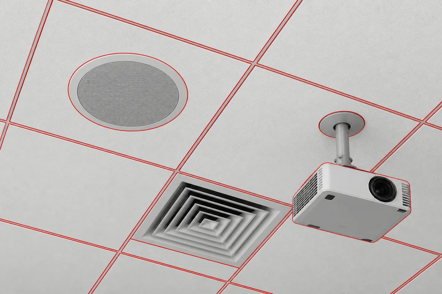
A reflected ceiling plan shows the ceiling as though it were mirrored on the floor below, so that it reads in the same orientation as the floor plan beneath it. For audio-visual work it is the drawing where the system meets everything else in the building. In many rooms the ceiling carries more equipment than any other surface, and it is among the hardest to change once it is built.
What competes for the ceiling
Audio-visual devices are late arrivals to a surface that is already busy:
- Ceiling speakers and ceiling microphones
- Projectors, mounts and drop poles
- Cameras, sensors and control devices
- Screens, and the access panels that serve them
- Lighting, ceiling grid and tiles, sprinklers, air diffusers, detectors, and the structure above all of it
Most of those have a position that somebody has already drawn. The reflected ceiling plan is where the positions are reconciled with each other.
What an audio-visual reflected ceiling plan has to show
- Device positions set out against the ceiling grid or a gridline, not described loosely
- Device types and tags that match the schedule and the schematic
- Mounting and fixing detail appropriate to the ceiling type
- The pathway by which cable reaches each device
- Access for later service
A device drawn without a dimension leaves its position to whoever installs it. That is not a criticism of site teams. It is a consequence of the drawing failing to answer the question.
Where the coordination happens
An audio-visual reflected ceiling plan is prepared against the architectural reflected ceiling plan rather than beside it. The architectural drawing sets the ceiling type, and the ceiling type decides what a device can fix to. A plasterboard ceiling, an exposed soffit and a suspended tile grid each call for different mounting detail for the same speaker.
The same drawing then has to sit alongside the lighting and services layouts. Where a ceiling speaker and an air diffuser want the same tile, the conflict is settled on the drawing or on site. Moving the speaker on site can change the coverage the system was designed to give.
Above the ceiling, the structure decides what can be supported and where pathways can run. Below it, the finished room is what the client sees. The reflected ceiling plan is where those two demands have to be satisfied together.
Why the drawing matters after installation
The ceiling is expensive to revisit. Once tiles are in, services are live and the room is finished, moving a ceiling-mounted device becomes a small job that behaves like a large one. Settling positions at the documentation stage keeps the change on the drawing, where it is an edit rather than a site operation.
The reflected ceiling plan also outlives the project. It tells a maintenance team what sits above the ceiling and where, and it tells the next project what it has to work around. Both of those readers usually come to the drawing after the people who prepared it have moved on, which is an argument for drawing it properly rather than adequately.
How we prepare them
Reflected ceiling plans appear in both of the drawing sets we produce. In audio-visual system design they document the ceiling-mounted devices. In architectural and construction drafting they document the ceiling itself, coordinated with lighting and services.
Where a project needs both, the same practice prepares both to the same drawing standard. The ceiling is then drawn once and agrees with itself, rather than arriving as two drawings that somebody on site has to reconcile.